
Replacing the subwoofer has been discussed at length here and elsewhere. But I wanted to bring this back up based on recent experiences. I took my EV6 to a car stereo shop to look into replacing the subwoofer following the previous advice. What I thought was going to be an easy upgrade ended up raising more questions.
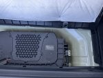
When they opened up the compartment to get a sense of what might be possible... there was a huge surprise. Not only was the sub not fastened at all, but there was a layer of insulation on the bottom of the compartment cover!
![]()
![]()
Thus, whatever sound the sub is generating is significantly muffled by the cover... which is in fact below another layer, the trunk floor! I actually just removed the cover for now, and the sub performance increased dramatically with bass set to 10. (They also attached the sub.") )
)
A few questions:
When they opened up the compartment to get a sense of what might be possible... there was a huge surprise. Not only was the sub not fastened at all, but there was a layer of insulation on the bottom of the compartment cover!

Thus, whatever sound the sub is generating is significantly muffled by the cover... which is in fact below another layer, the trunk floor! I actually just removed the cover for now, and the sub performance increased dramatically with bass set to 10. (They also attached the sub.
)A few questions:
- Did they install the wrong cover? Do others have this same insulated cover? Or is there a different cover that would make more sense with a sub? It just seems wrong.
- With the compartment cover and then the trunk floor over the compartment cover, that is a lot of muffling to overcome, even without the insulation. Is there some other solution for the trunk floor?
- The car stereo folks said that the recommended replacement would not make an appreciable difference in bass. They gave a quote of $1,600 which is well beyond what I wanted to spend. Can anyone provide feedback on whether the Rockwell SS8P (or some other active subwoofer that will fit into the space) makes an appreciable difference in bass?
- Finally, if they were to add on an amp, they questioned whether they could run a heavy gauge line from the 12V battery, given that the 12V adapter in the trunk is lightweight. Apparently Teslas will throw an error. Anyone have experience on that?